SuperFlow MV-50 air compressor - Disassembly, Upgrade, Reassembly
|
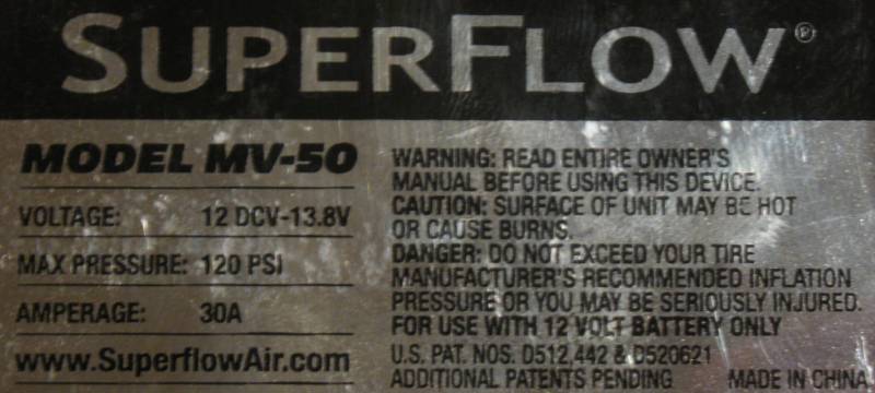
The SuperFlow (www.SuperflowAir.com)
MV-50
air compressor is noted for being a good bang-for-the-buck device. In
my case, the quality control of its manufacture caused me to repair it
upon first use (the two air gauge screws backed out). I did not need to
disassemble the complete unit to repair the air gauge, but with a few
"performance mods" found on the Internet, I figured I'd give them a
shot. I'm glad I disassembled the unit as the piston looked to be
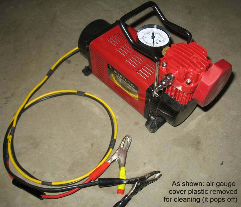
off-center of the cylinder which might cause a premature wear condition. Of note for the project are these items: 1) AIR GAUGE: Utilize thread locking compound on the air gauge screws 2) INTAKE PORT ENLARGEMENT: Open the air intake port for (hopefully*) greater flow performance 3) WIRING: Upgrade the wiring for (hopefully*) stronger motor performance 4) PISTON CENTERING: Fine-tune the assembled device (piston to cylinder centering, red housing "centering" plates adjusted) The air output connection was also changed to the same style the ARB air compressor utilizes. I can carry one hose for use on either device. * I say hopefully as I did not perform any before/after tests. This was due, somewhat, to the issue that the air gauge screws became dislodged on the first use of the device (airing up four 35" x 12.5 x 15 KM tires from ~12PSIg to ~24PSIg). |
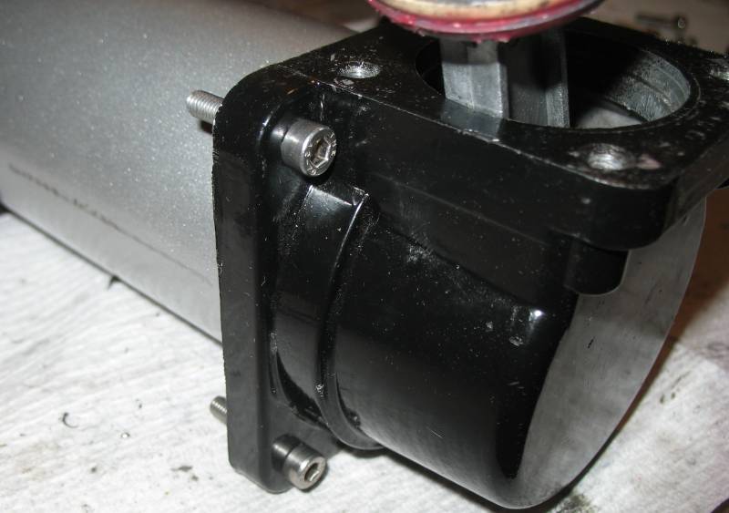
| Here is the unit as it now stands, post mods. |
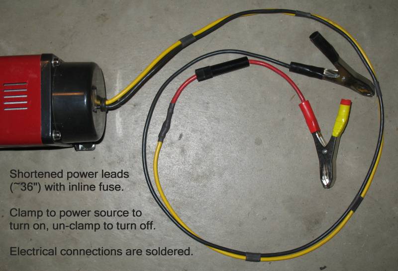
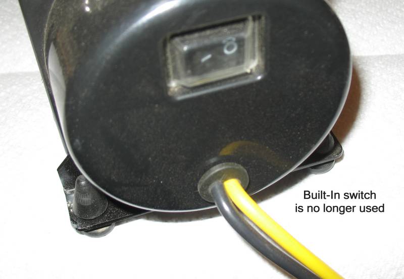
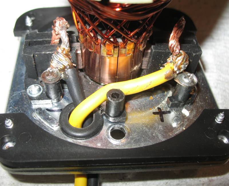
| The built-in switch is no longer used as it was too tight / difficult to work with the larger wiring in the confined space with the relay. Removing the switch from the electrical circuit also removed the need for the relay. Now, the wiring is straight to the motor brushes (depicted below). |
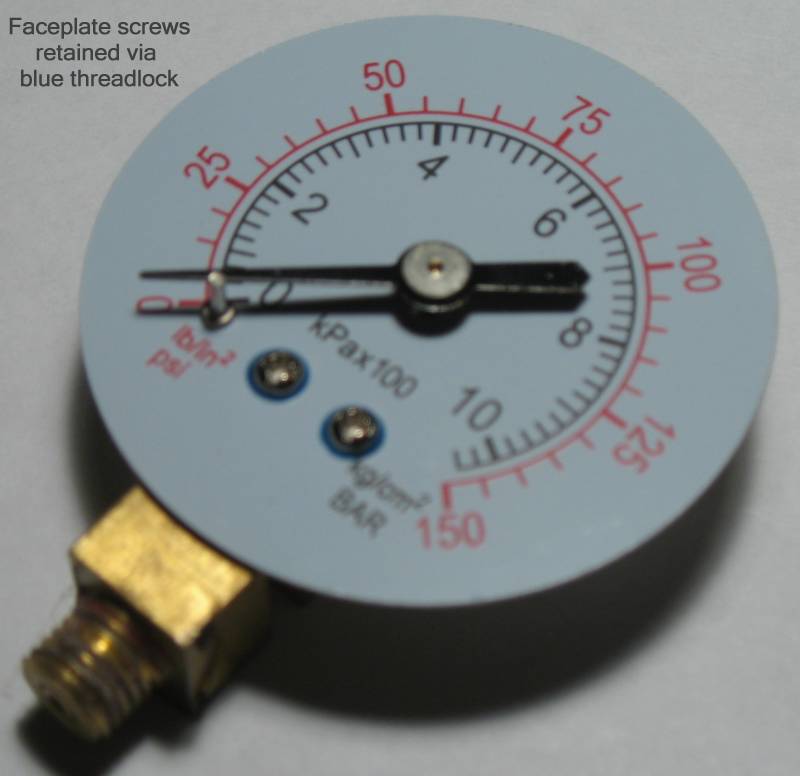
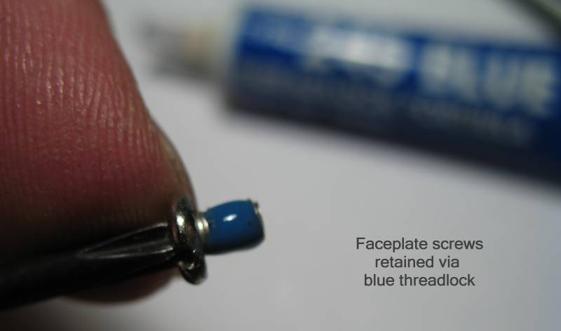
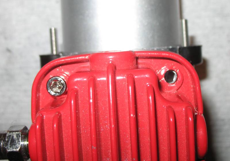
| AIR GAUGE Air gauge with faceplate screws fastened. |
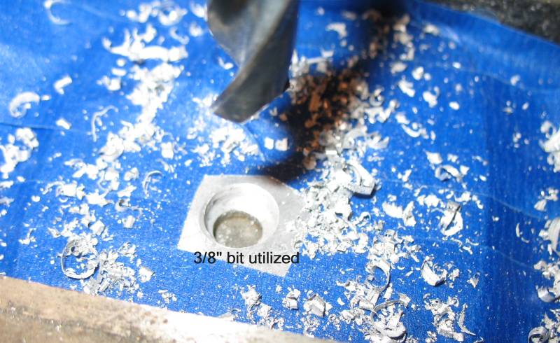
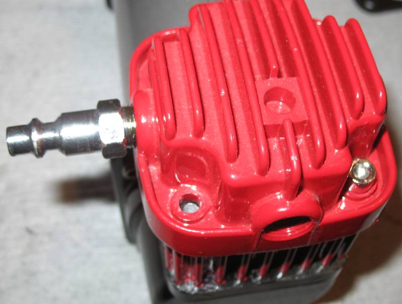
| INTAKE PORT ENLARGEMENT |
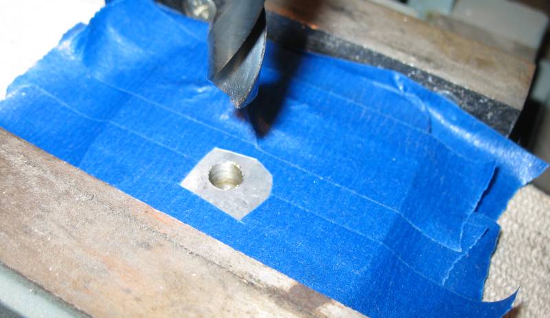
| Utilized a 3/8" drill to open up the intake port, paying attention to not harm the intake valve assembly. |
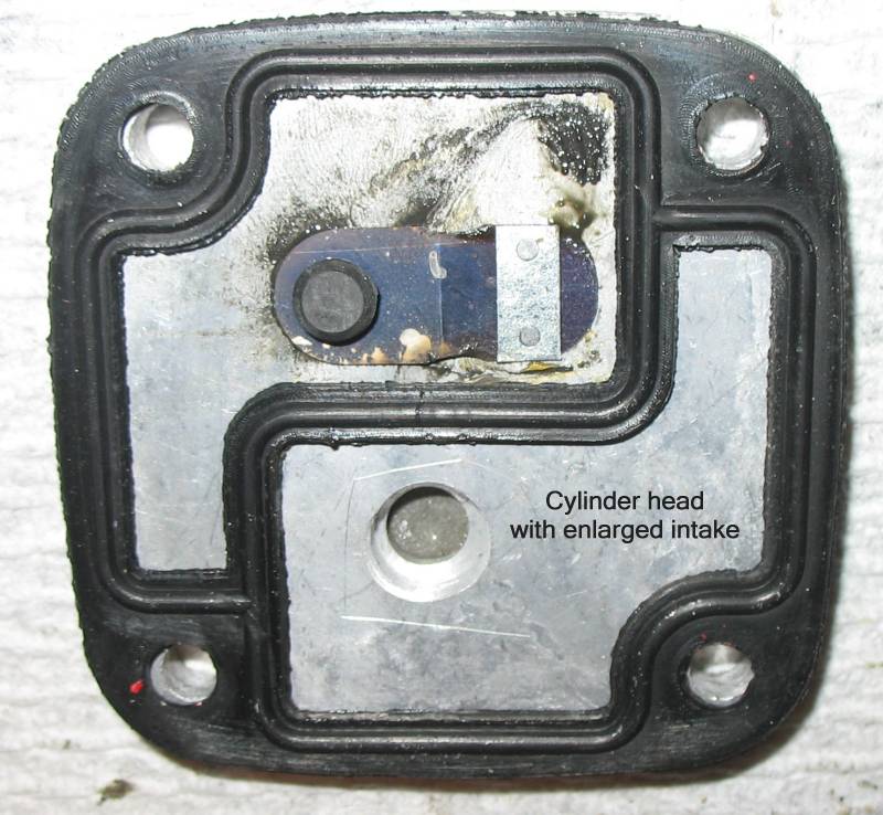
| Cylinder head with enlarged intake port. |
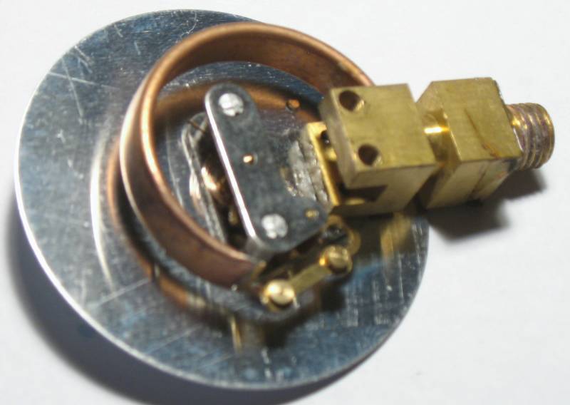
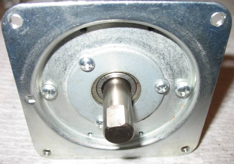
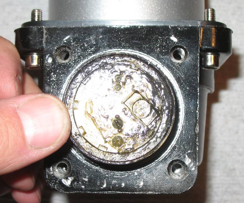
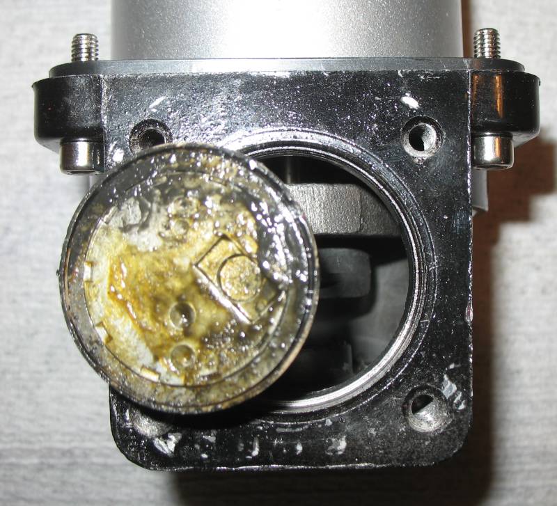
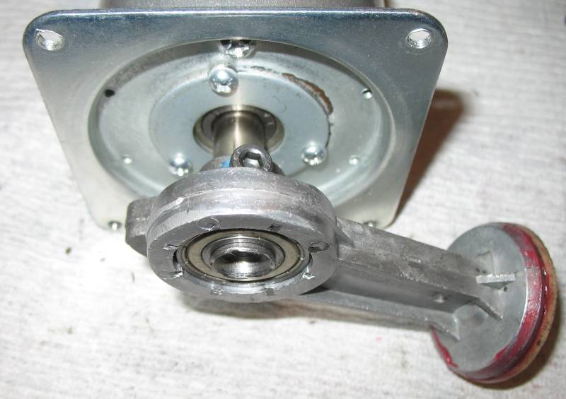
| WIRING Motor output shaft showing how the connecting rod fastens to it (set screw). |
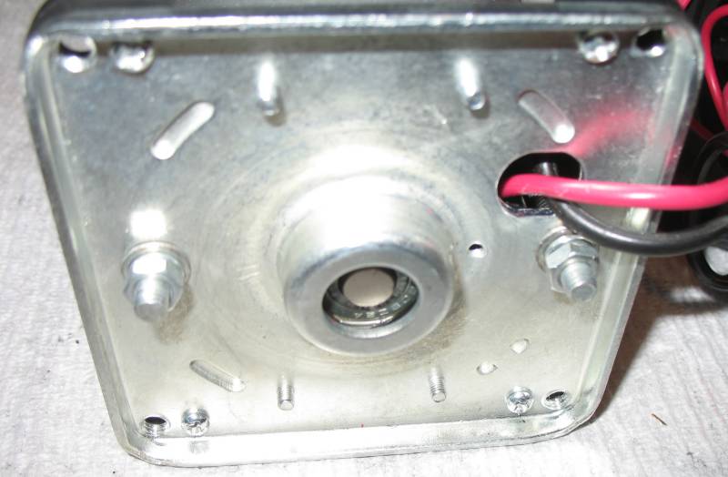
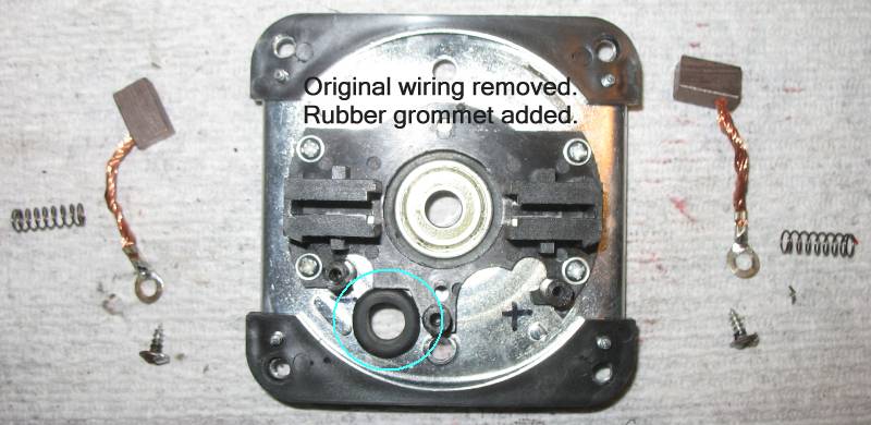
| Motor end, brushes. |
.
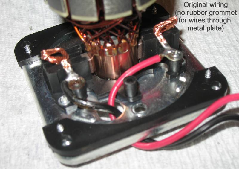
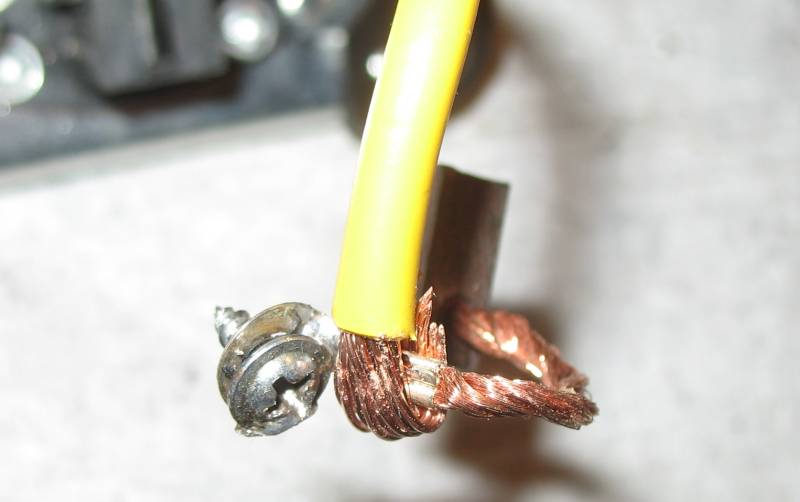
| Original wiring for the motor - supply wiring soldered to brush connectors. No rubber grommet where the wiring passed through the metal end plate. |
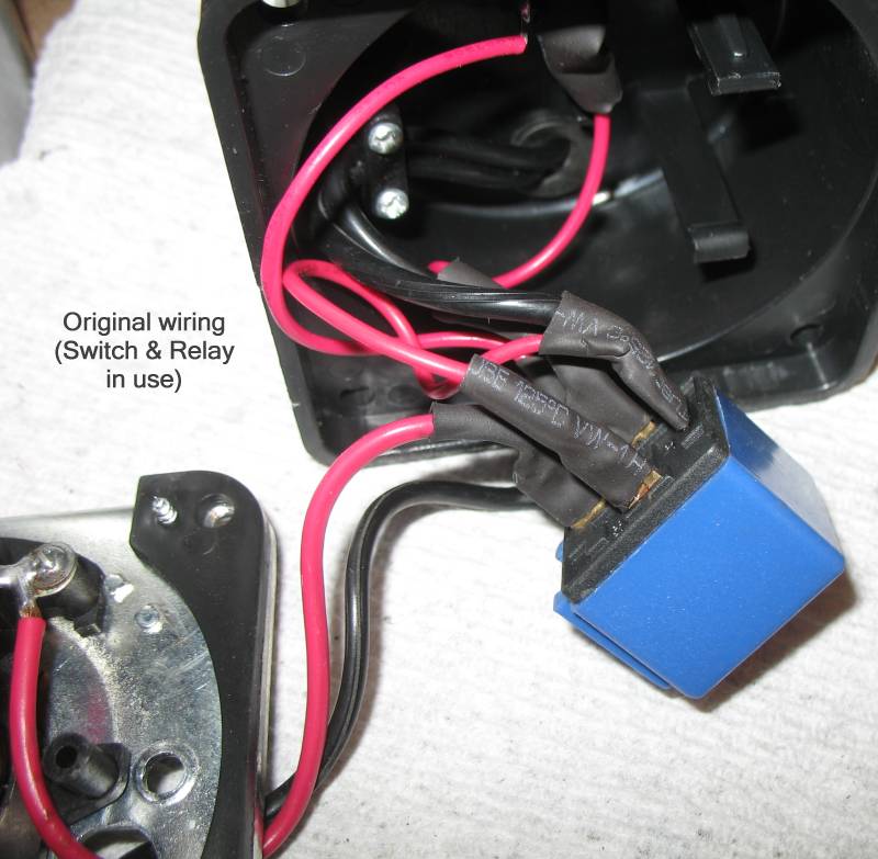
| Original wiring with the relay. The relay will be discarded and the switch disconnected (but left in the endcap to not have a hole) |
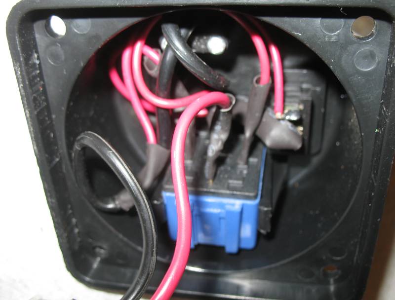
| Wiring endcap with switch and relay. |

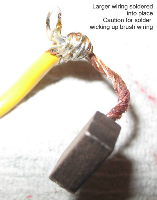
| It might be asked what gauge of wire did I use. I think I went with 10 or 12 gauge but I am not sure (I did the mod months ago). |
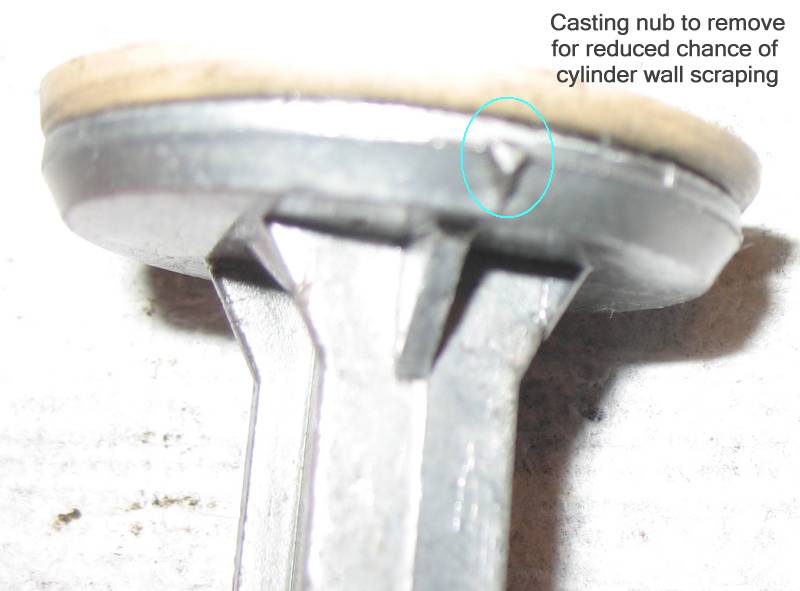
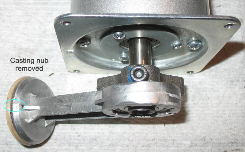
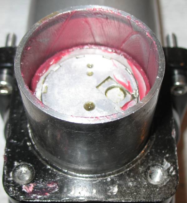
| With the piston removed, a casting nub protruded more than I cared for so it was removed. |
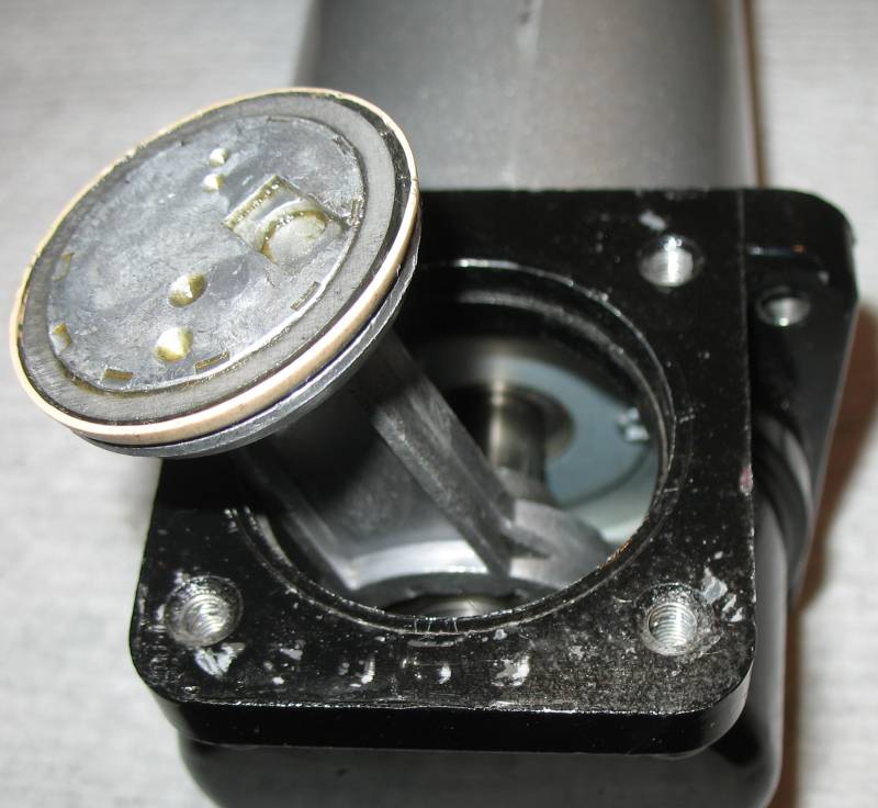
| Piston cleaned, preparing to measure / adjust for centering. |
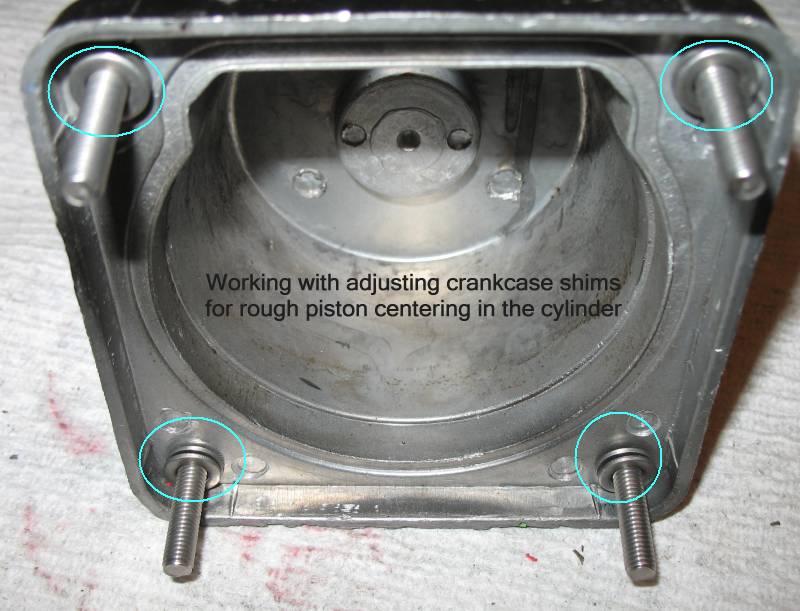
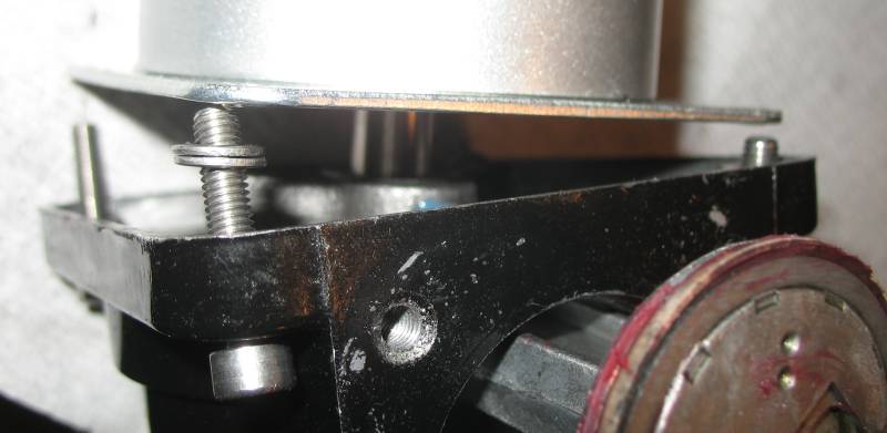
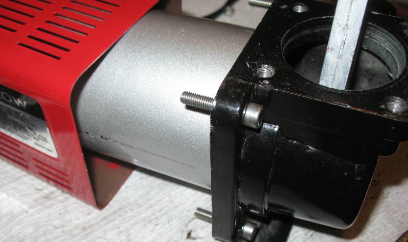
| I found that I could not properly center the piston in the cylinder without having the connecting rod to motor output shaft connection being at the far end of the motor's output shaft. I feared that the set screw would not have enough to hold onto. A fix for this would be to "move" the crankcase away from the end of the motor's output shaft. I added two "rough centering" washers to each crankcase to motor housing bolt. I believe I also needed longer bolts for the task. |
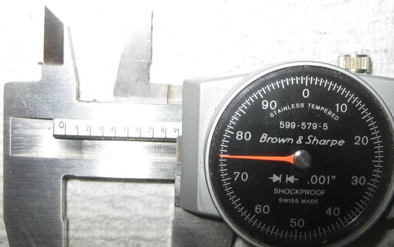
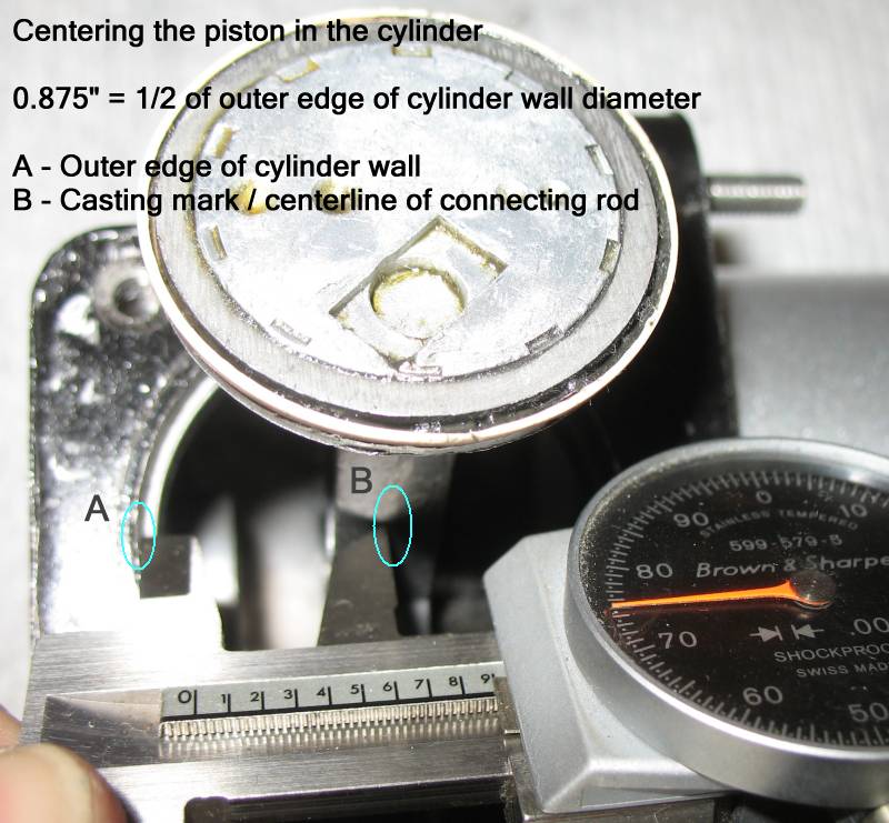
| 0.875 is 1/2 of the outer diameter of the piston's cylinder. |
| Measure / check / triple-check from one side of the cylinder wall to connecting rod centerline and from the other side of the cylinder wall to the connecting rod centerline. |
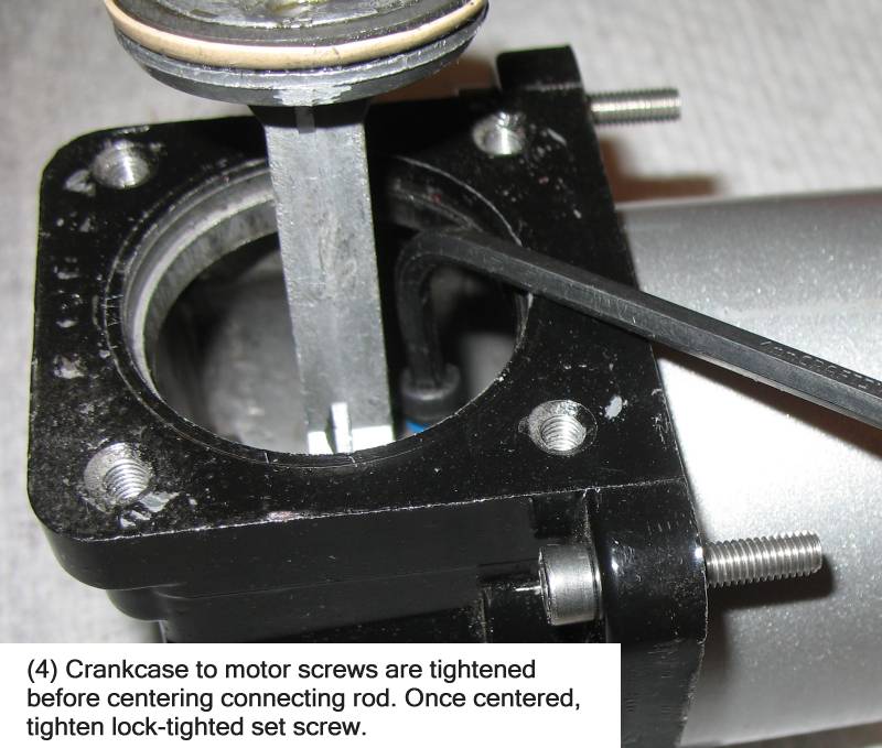
| With the piston centered, tighten the set screw with thread lock (and measure / check again). |
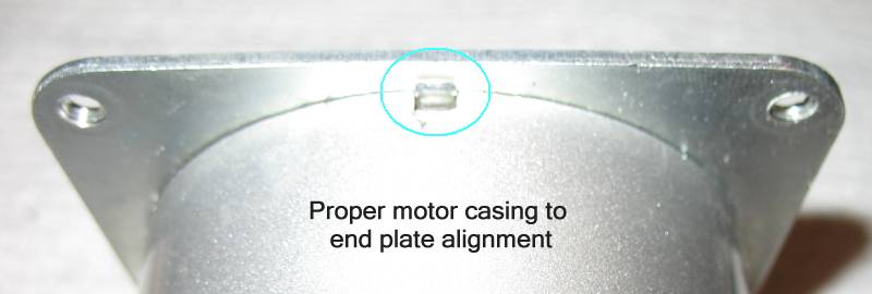
| The crankcase can be removed with the piston affixed to the motor. Pay attention to the location (if any are used) of the crankcase shim washers. |
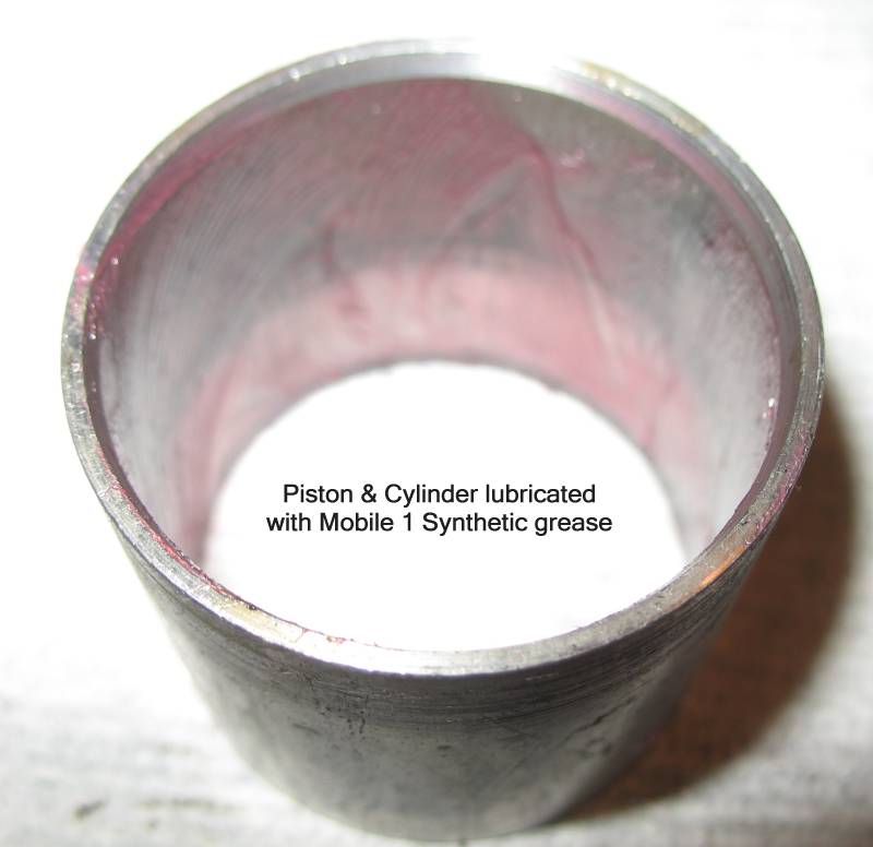
| Flat end of the cylinder goes to "top" of the cylinder (for good o-ring sealing surface at the head). |
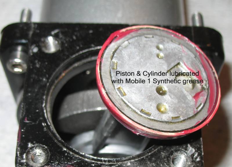
| Working end is assembled. |
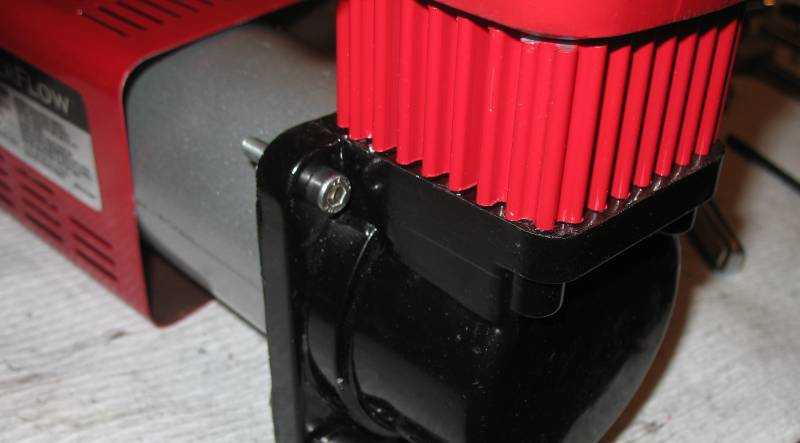
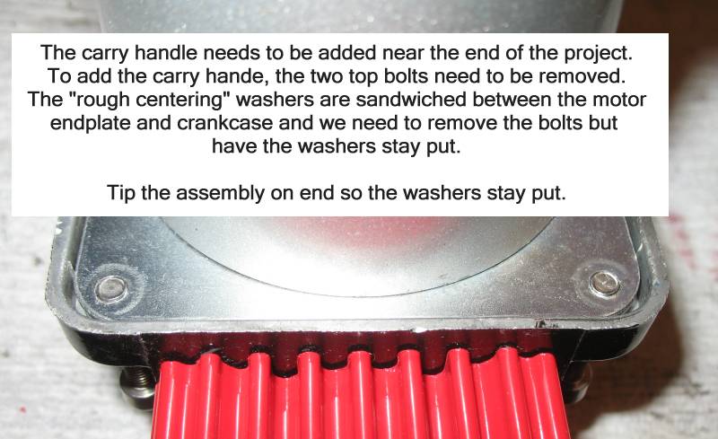
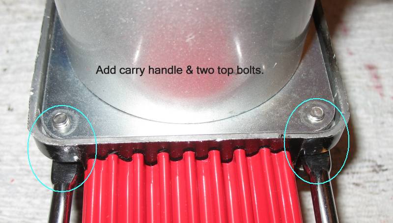
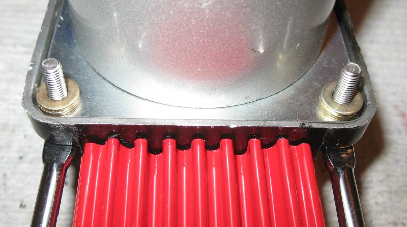
| Adding the carry handle (optional, but I find it convenient as the unit does get hot) |
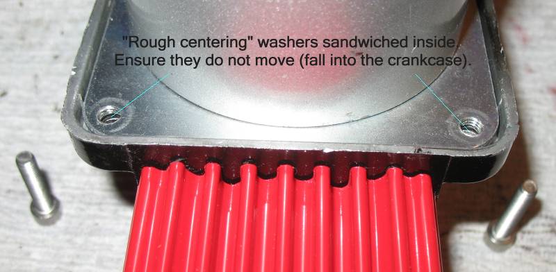
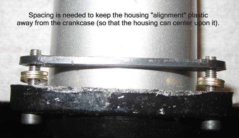
| The plastic piece is used to center the square red outer housing. It needs a couple washer to make it sit outboard from the crankcase. |
(c) Jim Williamson 2012
www.JimWilliamson.net